Chapter 13 Geological Structures and Mountain Building
Adapted from Physical Geology, First University of Saskatchewan Edition (Karla Panchuk) and Physical Geology (Steven Earle)
. Click the image for more attributions._](figures/13-geological-structures-and-mountain-building/figure-13-1.png)
Figure 13.1: Folded rocks in the Cariboo Mountains of BC. Source: Karla Panchuk (2018) CC BY-NC-SA 4.0. Photograph by Drew Brayshaw (2009) CC BY-NC 2.0 view source. Click the image for more attributions.
Learning Objectives
After reading this chapter and answering the review questions at the end, you should be able to:
- Describe the types of stresses that affect rocks.
- Explain how rocks respond to those stresses through brittle, elastic, or plastic deformation.
- Explain how rocks become folded and know the terms used to describe fold characteristics.
- Describe the conditions under which rocks fracture.
- Describe the different types of faults (normal, reverse, thrust, strike-slip) and the stresses that create them.
- Describe the different ways in which deformation of Earth’s lithosphere builds mountains.
- Measure the strike and dip of a geological feature, and plot the information on a map.
Folds, like those in the centre of Figure 13.1, are a common feature of mountain belts. Have you ever wondered how something as hard as rock could flex and bend to make folds, and what forces are required? Geologists have.
Observing and analysing geological structures helps us to understand the kinds of forces that affect rocks, both on small scales, and on scales as large as tectonic plates. With that knowledge we can understand how plate tectonic processes change the shape of Earth’s lithosphere. We can also piece together a history of past changes, including how mountain belts are formed. Structural geologists make careful observations of the orientations of breaks and bends in rocks, and can compile those measurements into maps of geological structures. These maps can be valuable tools for finding mineral resources.
13.1 Stress and Strain
Plate collisions and the accumulated weight of overlying rocks exert forces on rocks at depth. While the size of the force is important, it also matters whether the force is distributed over a wide region, or tightly focused on a small area. The same force will have a greater effect when acting over a small area than when acting over a larger area. If you have ever used snowshoes to walk across a snow bank without sinking in, you have taken advantage of the effects of distributing force (your mass acted upon by gravity) over a wider area (the area of your snowshoes rather than the soles of your boots). Stress is force adjusted for the area over which it is distributed. Strain is the change in shape that happens when rocks are deformed by stress.
13.1.1 Types of Stress
Stresses fall into two categories: normal stress acts at right angles to a surface, and shear stress acts parallel to a surface (Figure 13.2). Normal stress is subdivided into compression, when the stresses are squeezing a rock, and tension, when stress is pulling it apart. Rocks undergo compression in regions where plates are colliding, or where they are being buried beneath other rocks. Rocks experience tension where divergence is happening, such as when a continent is beginning the rifting process. Shear stress is characteristic of transform plate boundaries, where plates are moving side by side.
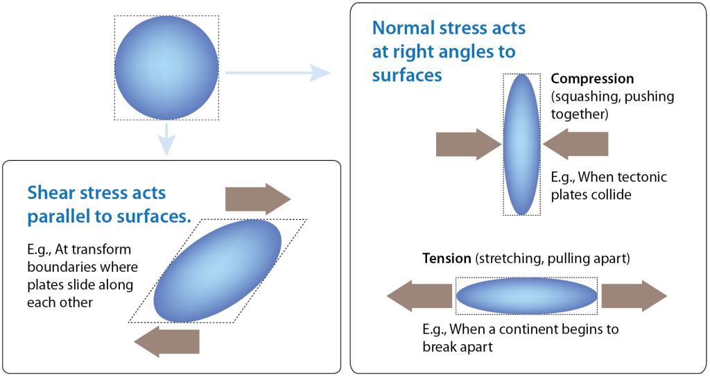
Figure 13.2: Rocks can be affected by normal stress (compression and tension) or shear stress. Source: Karla Panchuk (2016) CC BY 4.0
Although Figure 13.2 shows only one set of stress arrows for each scenario, rocks within the Earth are subject to stress from all directions. The relative size of the stresses in different directions will determine the response of the rock. Consider a deeply buried rock being stretched as a continent breaks apart (Figure 13.3). It is also being compressed by the weight of overlying sediments and rocks, but the stress from compression is relatively small compared to the tension from rifting. The net effect of stress acting on the rock will be determined more by the tension from rifting than by the compression from overlying rocks.
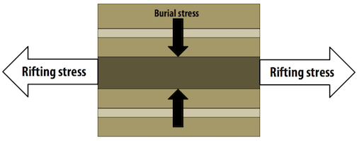
Figure 13.3: A rock layer (dark brown) is compressed by the weight of rocks above, and stretched by rifting. The sizes of the arrows indicate the relative sizes of the stresses. Source: Karla Panchuk (2018) CC BY 4.0
Rocks experience stress from all directions, but it is possible to break down stresses into three directions, just like a graph with x, y, and z axes. In diagrams showing these three directions, the sizes of arrows representing each direction will indicate the relative size of stresses, as they do in Figure 13.3. Analyzing stress in this way makes it much easier to describe the stresses operating on a rock, and to understand what their net effect will be.
13.1.2 Types of Strain
How a rock responds to stress depends on many factors. The “how” is not simply a matter of how much strain a rock will undergo, but what type of strain will occur. Is the deformation permanent or temporary? Does the rock break or does it deform without breaking?
13.1.2.1 Elastic Strain
Elastic strain is reversible strain. You can think of elastic strain as what happens to the elastic waistband of your favourite sweatpants when you put them on. The elastic stretches to let you into your pants, and once you’re in them, it shrinks to keep them from falling down. When you take the pants off again, the elastic goes back to its original shape. Similarly, rocks undergoing elastic strain will snap back to their original shape once the stress is removed. Rocks snapping back to their original shape undergo elastic rebound. Elastic rebound of rocks on a large scale can have profound consequences, because the energy released causes the Earth to vibrate. We experience those vibrations as earthquakes.
13.1.2.2 Plastic Strain
If enough stress is applied, the changes that a material undergoes to accommodate the stress will leave it permanently deformed. When the stress is removed, the material does not go back to its original shape. The permanent deformation is called plastic strain.
13.1.2.3 Ductile or Brittle?
Ductile deformation refers to deformation that happens by flowing or stretching. The marble monument in Figure 13.4 is undergoing ductile deformation as it sags beneath its own weight.
_](figures/13-geological-structures-and-mountain-building/figure-13-4.jpeg)
Figure 13.4: A marble monument at the Westminster Hall and Burying Ground in Baltimore, Maryland. The horizontal surface is undergoing slow ductile deformation as it sags beneath its own weight. The author Edgar Allan Poe is interred nearby. Source: Ray Pennisi (2007) CC BY-NC 2.0 view source
When a material breaks, it has undergone brittle deformation (Figure 13.5). The stone cylinders in Figure 13.5 are part of an experiment to test the strength of the rock. The cylinder on the right looked like the cylinder on the left before it was compressed, with force applied to the top and bottom. Strain gauges have been glued on to measure the amount of deformation lengthwise and across the cylinders.
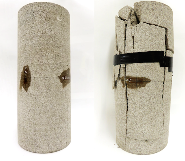
Figure 13.5: Cylinders of rock used to test the strength of rock under compression. The cylinder on the left has been equipped with strain gauges to measure the amount of deformation. The cylinder on the right has undergone brittle deformation after being compressed. Source: Karla Panchuk (2016) CC BY 4.0
A material can undergo more than one kind of deformation when stress is applied. The barrel-shaped cylinder of potash in Figure 13.6 (right) originally looked like the cylinder on the left. The cylinder was compressed, with stress applied from the top and bottom. Initially, it underwent ductile deformation and thickened in the middle, creating the barrel shape. But as more stress was applied, the cylinder eventually underwent brittle deformation, resulting in the crack across the middle.
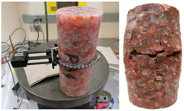
Figure 13.6: Cylinders of potash before and after deformation. The potash underwent ductile deformation before it finally broke. Source: Karla Panchuk (2018) CC BY 4.0
13.1.3 Factors That Determine How A Rock Will Deform
A rock is not limited to exclusively brittle deformation, or exclusively ductile deformation. Even the deformed rock in Figure 13.5, which has clearly undergone brittle deformation, shows a slight curvature on the right side, near the top. This indicates that a small amount of ductile deformation occurred before brittle failure.
For a given rock, deformation will be different depending on the amount of stress applied. Up to a point, rocks undergo elastic deformation, and will spring back to their original shape after the stress is removed. If more stress is applied, the rock may deform in a ductile manner. If stress increases further, the rock may fracture. The amount of stress required in each case will depend on the type of rock, as well as conditions such as pressure and temperature.
13.1.3.1 Composition
In general, sedimentary rocks will be more likely to undergo ductile deformation than igneous or metamorphic rocks under the same conditions. Rocks within each group will also deform differently.
Boudinage structures (Figure 13.7) highlight the effect of composition on how rocks deform. These structures occur when a stronger rock more prone to brittle deformation is surrounded by weaker rocks prone to ductile deformation. The stronger rock will fracture into segments, called boudins, and the weaker rock will flow into the spaces between. In Figure 13.7 (top), the white layer reached the stage of pinching off, just before separating into segments. The surrounding black layer flowed in to fill the gap where the pinch was happening. Remarkably, the white layer itself contains a dark layer that has fragmented into boudins. Not all boudins break into blocky segments. Some display more ductile deformation (Figure 13.7, bottom).
. Bottom- Joyce McBeth (n.d.) CC BY 4.0 _](figures/13-geological-structures-and-mountain-building/figure-13-7.png)
Figure 13.7: Two examples of boudinage structure. Top- The white layer has pinched off into segments, and the surrounding black layers have flowed into the gap forming between segments. Within the white layer is a thinner black layer that has also broken into segments. Bottom- Boudins displaying ductile deformation. Source: Top- Marek Cichanski (2012) CC BY-NC 2.0 view source. Bottom- Joyce McBeth (n.d.) CC BY 4.0
13.1.3.2 Temperature and Pressure
At higher temperatures, and under higher confining pressures, rocks are more likely to undergo ductile deformation. Confining pressure is the stress that a material experiences uniformly from all sides as a result of the weight of material above and around it. The pressure that a diver feels deep in the ocean is confining pressure due to the weight of water above and around the diver. This kind of confining pressure is called hydrostatic pressure. Within Earth, the confining pressure is due to the weight of overlying rocks. Confining pressure due to the weight of rocks is called lithostatic pressure.
The rocks in Figures 13.5 and 13.6 experienced confining pressure from the atmosphere, and temperatures comfortable for the humans working in the lab. Under those conditions the rocks ultimately underwent brittle failure when they were compressed in the lab. Deep within the crust, the temperatures and confining pressures are far greater. Deep enough within the crust, both samples would undergo only ductile deformation if the same amount of stress were applied as in the experiment. The depth at which temperatures and confining pressures are high enough for rocks to go from brittle deformation to ductile deformation is called the brittle-ductile transition zone.
The brittle-ductile transition zone occurs between approximately 10 km and 30 km depth, corresponding to temperatures around 300 ºC and greater. The depth at which temperatures reach 300 ºC at any particular location will depend on heat flow at that location. In continental crust, rocks at 300 ºC are deeper than in ocean crust. The change in pressure with depth also varies, depending on the mass and density of rocks. If depths are measured relative to sea level, the pressure at 10 km measured beneath a tall mountain belt will be greater than the pressure at 10 km measured within ocean crust.
Experiments like those shown in Figures 13.5 and 13.6 can be used to determine where the brittle-ductile transition zone will be for a particular rock type. Experimenters apply stress to sample of a rock for a range of temperatures and confining pressures. They note the conditions under which the rock breaks or deforms in a ductile manner, and plot those on a graph (Figure 13.8). The results in Figure 13.8 are from experiments on limestone. The vertical axis is pressure. The more pressure, the deeper the rock would have to be within the Earth to experience that pressure. The white line represents the brittle-ductile transition zone. Above the white line are pressures and temperatures under which the limestone would fracture. Below the white line in the tan area are pressures and temperatures where the limestone would deform by flowing. Notice that the higher the temperatures, the less confining pressure is required for ductile deformation.
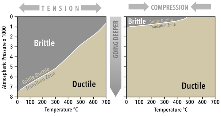
Figure 13.8: Experimental results on limestone with tension applied (left) and compression applied (right). Source: Karla Panchuk (2018) CC BY 4.0 modified after Heard (1960)
13.1.3.3 How Stress Is Applied
The limestone experiments were performed by applying stress as tension (Figure 13.8 left) and again by applying stress as compression (right). When tension was applied, temperature and confining pressure had to be much higher before ductile deformation occurred. Under compression, ductile deformation was possible with far less confining pressure, and at lower temperatures.
Strain rate, the rate at which deformation occurs, also makes a difference. If stress is applied at a rate that causes rapid deformation, the rock will be more likely to fracture than if deformation happens slowly. The marble slab in Figure 13.4 is a good example of this. It has sagged rather than broken because the rate of deformation has been very slow, at millimetres per decade.
13.1.3.4 Fluids
When rocks are under pressure, fluids trapped within the pore spaces of rocks- the gaps between grains- are also under pressure. Higher confining pressure is required for deformation to be ductile rather than brittle, but pressure from fluids, called pore pressure, resists the confining pressure. The result is that the effective confining pressure is lower than it would be without the fluids. Depending on the amount of pore pressure, and how close the rock is to the brittle-ductile transition zone, pore pressure could cause brittle failure in a rock that would otherwise undergo ductile deformation.
13.1.4 Stress and Geological Structures
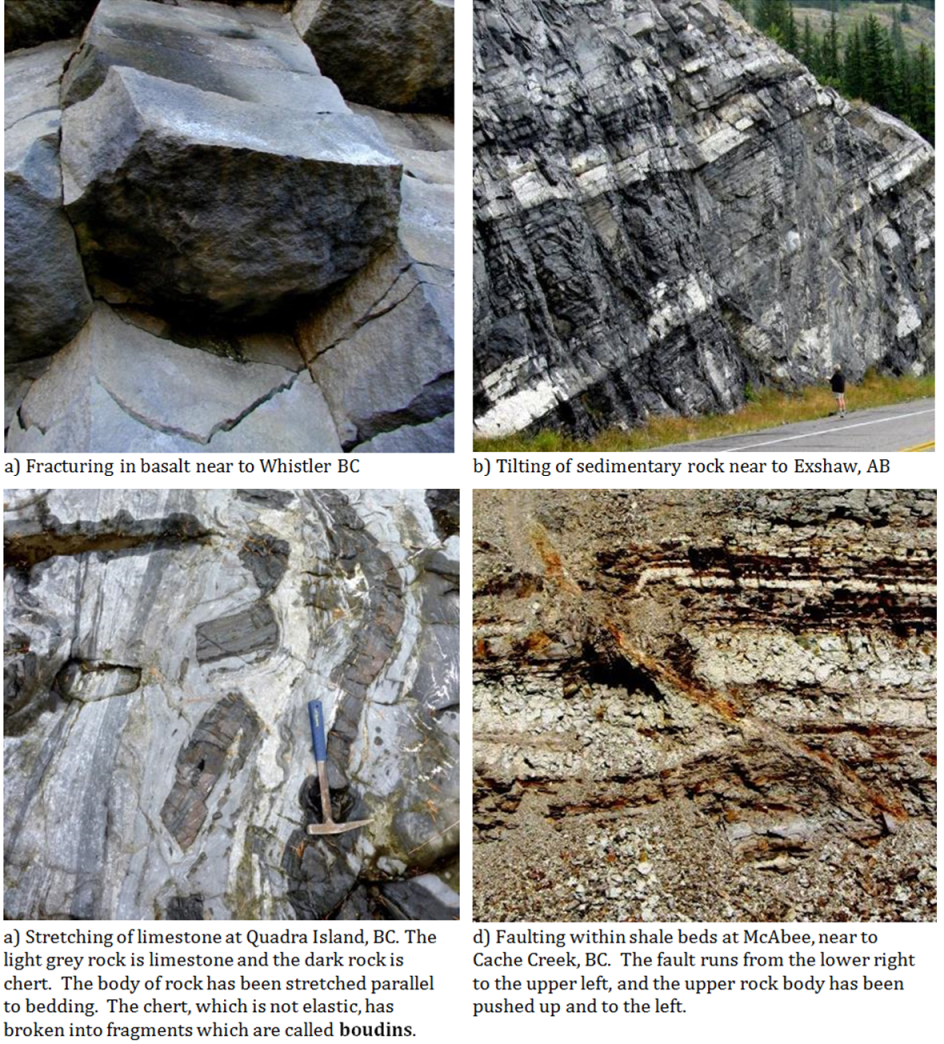
Many different geologic structures can form when stress is applied to rocks. Structures form as a result of fracturing, tilting, folding, stretching, and squeezing (Figure 13.9). Some structures, like the fractures that make basalt columns (Figure 13.9, upper left), happen when rocks shrink due to cooling, but others are a consequence of plate tectonic forces. The types of structures that form depend on the plate tectonic setting and other geological conditions, making them valuable tools for understanding what happened to the rocks. The following sections address the different kinds of structures that form, and what information we can gather from these structures to learn more about the tectonic environment and regional geology.
_](figures/13-geological-structures-and-mountain-building/figure-13-9.png)
Figure 13.9: Structures resulting from deformation. Upper left- Fracturing in basalt near Whistler, British Columbia. Upper right- Tilting of sedimentary rock near Exshaw, Alberta. Lower left- Stretched limestone (light grey) and chert (dark grey) from Quadra Island, British Columbia. Lower right- Faulted shale near Cache Creek, British Columbia. Rocks above the fault moved up relative to those below. Source: Karla Panchuk (2018) CC BY 4.0. Photographs by Steven Leslie (2015) CC BY 4.0 view source
13.2 Folds
Folds are a type of ductile deformation. They form when rocks bend in response to stress. The sides of a fold are its limbs (Figure 13.10). The limbs meet in a region of curvature called the hinge zone. A fold’s axial surface is an imaginary surface that runs along the hinge zone and cuts the fold in half. The line that forms when the axial surface intersects another surface, such as the top of a bed, is called the axial trace. Axial traces are sometimes marked on geological maps to show the location of the fold’s hinge zone.
_](figures/13-geological-structures-and-mountain-building/figure-13-10.png)
Figure 13.10: The parts of a fold. A fold consists of limbs that meet at the hinge zone. An axial surface bisects the fold along the hinge zone. The axial trace is where the axial surface intersects another surface, such as the top of a bed. Source: Karla Panchuk (2018) CC BY-NC-SA 4.0. Photo: Ron Schott (2009) CC BY-NC-SA 2.0 view source
13.2.1 Fold Classification
13.2.1.1 Synclines and Anticlines
Folds can be classified according to the whether the limbs slope toward or away from the hinge zone. If the limbs slope toward the hinge zone (i.e., the hinge zone points downward), as in the fold in the left of Figure 13.11, the fold is called a syncline. If the limbs slope away from the hinge zone (i.e., the hinge zone points upward), the fold is called an anticline. There is an anticline on the right side of Figure 13.11. The fold in Figure 13.10 is also an anticline. Sometimes an anticline or a syncline will occur by itself, but they can also occur in a series of alternating synclines and anticlines, similar to the way the anticline and syncline share a limb in Figure 13.11. A sequence of linked anticlines and synclines is called a fold train.
_](figures/13-geological-structures-and-mountain-building/figure-13-11.png)
Figure 13.11: An asymmetrical syncline linked to an anticline on a beach in Cornwall, United Kingdom. The beds slope toward the hinge at different angles on either side of the axial surface. Source: Karla Panchuk (2018) CC BY-NC-SA 4.0. Photo: Harry Soar (2014) CC BY-NC-SA 2.0 view source
13.2.1.2 Symmetrical, Asymmetrical, Overturned, and Recumbent
In a symmetrical fold, the limbs slope at approximately the same angle on either side of the axial surface. The fold in Figure 13.10 is symmetrical. In an asymmetrical fold, the limbs slope at different angles on either side of the axial surface. The syncline in Figure 13.11 is asymmetrical. The limb on the left side of the syncline slopes toward the hinge at a steeper angle than the limb on the right.
If the fold is sufficiently tilted that the beds on one side have been tilted past vertical, and are sloping in the same direction, the fold is overturned (Figure 13.12).
_](figures/13-geological-structures-and-mountain-building/figure-13-12.png)
Figure 13.12: Overturned folds in Andalusia in southern Spain. Some limbs have been overturned far enough to be sloping in the same direction on either side of the axial trace. Source: Karla Panchuk (2018) CC BY-NC-SA 2.0. Photo: Ignacio Benvenuty Cabral (2017) CC BY-NC-SA 4.0 view source
It is possible for rocks to be folded so tightly that the fold limbs are nearly parallel. Folds with parallel limbs are called isoclinal folds. A recumbent fold is an isoclinal fold that has been overturned to the extent that the limbs are horizontal (Figure 13.13).
_](figures/13-geological-structures-and-mountain-building/figure-13-13.png)
Figure 13.13: A recumbent fold has limbs that are nearly parallel, and an axial trace that is nearly horizontal. Source: Karla Panchuk (2018) CC BY-NC-SA 4.0. Photo: Ignacio Benvenuty Cabral (2017) CC BY-NC-SA 4.0 view source
13.2.2 Folds in the Landscape
Folds can be of any size, and it’s very common to have smaller folds within larger folds (Figure 13.14). Large folds can extend over 10s of kilometres, and very small ones might only be visible under a microscope.
_](figures/13-geological-structures-and-mountain-building/figure-13-14.jpg)
Figure 13.14: Folded limestone (grey) and chert (rust-coloured) in rocks of the Triassic Quatsino Formation on Quadra Island, British Columbia. The image is about 1 m across. Source: Steven Earle (2015) CC BY 4.0 view source
When folded rocks are weathered and eroded, they can alter the landscape by forming long ridges and valleys (Figure 13.15). Ridges and valleys curve into V-shapes if the hinge of the fold is not horizontal. A fold with a hinge that slopes downward is called a plunging fold (Figure 13.16).
_](figures/13-geological-structures-and-mountain-building/figure-13-15.png)
Figure 13.15: Ridges and valleys in central Pennsylvania formed from weathered and eroded folds. The V-shapes indicate the folds are plunging. Source: NASA on the Commons (2001) Public Domain view source
_](figures/13-geological-structures-and-mountain-building/figure-13-16.png)
Figure 13.16: Plunging folds have sloping hinges. Plunging folds are described in terms of the plunge angle, the angle the hinge makes with a horizontal line. Inset- When a plunging fold intersects a surface, the result is a V-shaped pattern._ Source: Karla Panchuk (2018) CC BY-SA 4.0. Photo- Dieter Mueller (2004) CC BY-SA 3.0 view source_
Folds can create landforms, but anticlines are not necessarily expressed as ridges in the terrain. Likewise, synclines do not necessarily appear as valleys. When folded rocks erode, the landform that results depends how resistant individual layers are to erosion. For example, if the rocks in the interior of an anticline are more resistant to weathering than the surrounding rocks, a ridge will result (e.g., the low hill represented by units 4 and 5 in Figure 13.17, top). On the other hand, if rocks in the interior of the anticline are weaker, a valley will result (Figure 13.17, bottom, units d1 and d2). Similarly, a syncline with stronger rocks in the interior will weather to form a ridge, and a syncline with weaker rocks in the interior will weather to form a valley.
 / _[_Bottom_](https://archive.org/stream/recordsofrocksor00symoiala#page/194/mode/2up)](figures/13-geological-structures-and-mountain-building/figure-13-17.png)
Figure 13.17: Cross-sections of eroded folds expressed as hills and valleys, from an early study on the geology of Wales, Devon, and Cornwall. Top- An anticline in Shropshire, England. Beds in the interior of the anticline form a gentle hill. Bottom- An anticline in Herefordshire, England in which beds in the interior of an anticline weathered to form a valley. Source: Symonds (1872) Public Domain. View source: Top / Bottom
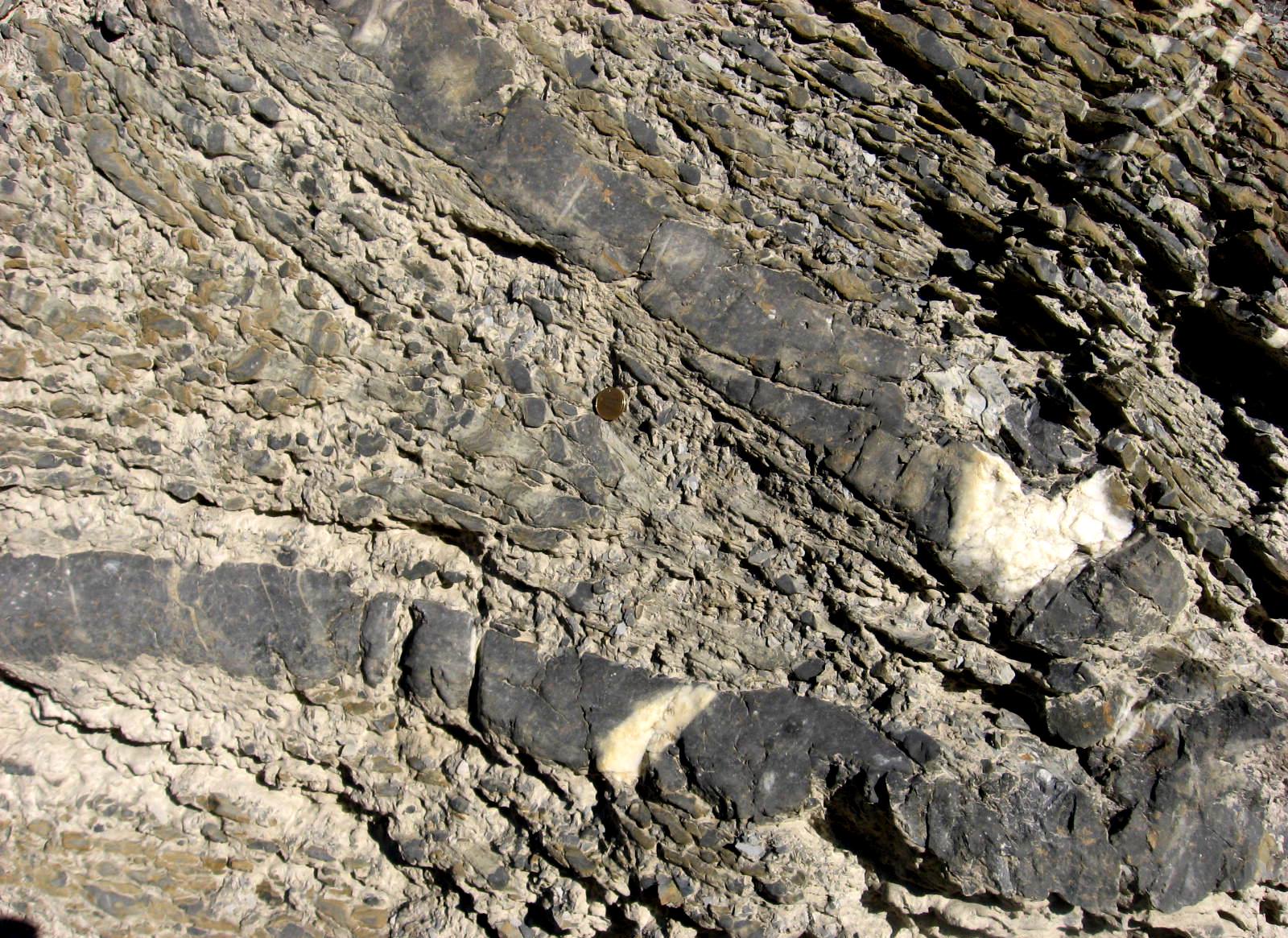
Exercise: Fold Types
What kind of folds are shown here? If you are finding it difficult to see the folds, follow the trace line formed by the white beds through the outcrop.
_](figures/13-geological-structures-and-mountain-building/figure-13-18.jpg)
Figure 13.18: Folds in the Rocky Mountains near Golden, British Columbia. Source: Steven Earle (2015) CC BY 4.0 view source
13.3 Fractures, Joints, and Faults
When rocks break in response to stress, the resulting break is called a fracture. If rocks on one side of the break shift relative to rocks on the other side, then the fracture is a fault. If there is no movement of one side relative to the other, and if there are many other fractures with the same orientation, then the fractures are called joints. Joints with a common orientation make up a joint set (Figure 13.19).
_](figures/13-geological-structures-and-mountain-building/figure-13-19.jpg)
Figure 13.19: Joint sets have broken these siltstone and shale beds into long rectangular planks. Source: Michael C. Rygel (2008) CC BY-SA 3.0 view source
13.3.1 Jointing
Most joints form when the overall stress regime is one of tension (pulling apart) rather than compression. The tension can be from a rock contracting, such as during the cooling of volcanic rock (Figure 13.9, upper left). It can also be from a body of rock expanding. Exfoliation joints, which make the rock appear to be flaking off in sheets (Figure 13.20), occur when a body of rock expands in response to reduced pressure, such as when overlying rocks have been removed by erosion.
_](figures/13-geological-structures-and-mountain-building/figure-13-20.jpg)
Figure 13.20: Half Dome at Yosemite National Park is an exposed granite batholith that displays exfoliation joints, causing sheets of rock to break off. Source: HylgeriaK (2010) CC BY-SA 3.0 view source
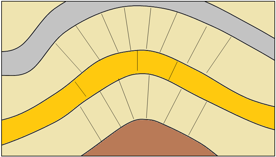
Nevertheless, it is possible for joints to develop where the overall regime is one of compression. Joints can develop where rocks are being folded, because the hinge zone of the fold is under tension as it stretches to accommodate the bending (Figure 13.21).
_](figures/13-geological-structures-and-mountain-building/figure-13-21.png)
Figure 13.21: Joints developed in the hinge zone of folded rocks. Source: Steven Earle (2015) CC BY 4.0 view source
Joints can also develop in a rock a rock under compression as a way to accommodate the change in shape (Figure 13.22). The joints accommodate the larger compression stress (larger red arrows) by allowing the rock to stretch in the up-down direction (along the green arrows).
_](figures/13-geological-structures-and-mountain-building/figure-13-22.png)
Figure 13.22: Joints developing to accommodate the larger horizontal component of compression (large red arrows). Source: Steven Earle CC BY 4.0 view source
Faulting
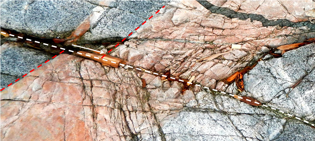
A fault is a boundary between two bodies of rock along which there has been relative motion (e.g., Figure 13.23). Some large faults, like the San Andreas fault in California or the Tintina fault, extending from northern British Columbia through central Yukon and into Alaska, show evidence of hundreds of kilometres of motion. Other faults show only centimetres of movement. In order to estimate the amount of motion on a fault, it is necessary to find a feature that shows up on both sides of the fault, and has been offset by the fault. This could be the edge of a bed or dike as in Figure 13.23, or it could be a landscape feature, such as a fence or a stream.
_](figures/13-geological-structures-and-mountain-building/figure-13-23.png)
Figure 13.23: View looking down on a fault (white dashed line) in intrusive rocks on Quadra Island, British Columbia. The pink dyke has been offset approximately 10 cm by the fault (length of the white arrow). Source: Steven Earle (2015) CC BY 4.0 view source
13.3.1.1 Types of Faults
Different kinds of faults develop under different stress conditions. We describe faults in terms of how the rocks on one side of the fault move relative to the other.
13.3.1.1.1 Dip-Slip Faults
Dip-slip faults are so named because the dominant motion involves moving up or down the dipping (tilting) fault plane. In dip-slip faults we identify rock above the fault as the hanging wall, (or headwall) and the rock beneath as the footwall. These terms were originally used by miners to describe the rocks above and below an ore body (Figure 13.24).
.jpeg). Diagram- Karla Panchuk (2018) CC BY 4.0_](figures/13-geological-structures-and-mountain-building/figure-13-24.png)
Figure 13.24: The hanging wall (or headwall) of a fault is the rock above the fault. The footwall is the rock below. These terms were originally used by miners to describe the rocks above and below an ore body. Source: Photo- Gold Hill Mine, Yukon Territory, by Eric A. Hegg (1898) Public Domain view source. Diagram- Karla Panchuk (2018) CC BY 4.0
Tension produces normal faults, in which the crust undergoes extension. This permits the hanging wall to slide down the footwall in response to gravity (Figure 13.25, left). Compression produces reverse faults, pushing the hanging wall up relative to the footwall. Reverse faults shorten and thicken the crust (Figure 13.25, right).
_](figures/13-geological-structures-and-mountain-building/figure-13-25.png)
Figure 13.25: Dip slip faults. Normal faults are caused by tension, while reverse faults happen during compression. Source: Karla Panchuk (2018) CC BY-SA 4.0, modifed after Woudloper (2010) CC BY-SA 3.0 view source
13.3.1.1.2 Strike-Slip Faults
Faults where the motion is mostly horizontal and along the “strike” or the length of the fault are called strike-slip faults (Figure 13.26 bottom). These happen where shear stress causes bodies of rock to slide sideways with respect to each other, as is the case along a transform boundary. If the far side moves to the right, as in Figures 13.23 and 13.26 (right), it is a right-handed, right-lateral, or dextral strike-slip fault. If the far side moves to the left it is a left-handed, left-lateral, or sinistral strike-slip fault.
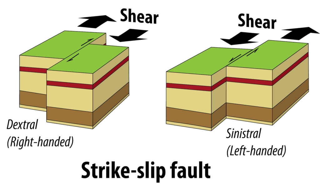
Figure 13.26: Strike-slip faults. Rocks on either side of the fault move parallel to the fault. In dextral strike-slip faults the far side moves to the right of the observer. In sinistral strike-slip faults the far side moves to the left of the observer. Source: Karla Panchuk (2018) CC BY 4.0
13.3.1.2 Different Tectonic Settings Have Distinct Types of Faults
13.3.1.2.1 Horst and Graben Structure
In areas that are characterized by extensional tectonics, and with many normal faults arranged side-by-side, some blocks may subside (settle downward) relative to neighbouring parts. This is typical in areas of continental rifting, such as the Great Rift Valley of East Africa or in parts of Iceland. In such situations, blocks that move down relative to the other blocks are graben, and elevated blocks with graben on either side are called horsts. There are many horsts and grabens in the Basin and Range area of the western United States, especially in Nevada. Part of the Fraser Valley region of British Columbia, in the area around Sumas Prairie, is a graben.
_](figures/13-geological-structures-and-mountain-building/figure-13-27.png)
Figure 13.27: Graben and horst structures form where extension is happening. All of the faults are normal faults. Source: Steven Earle (2015) CC BY 4.0 view source
13.3.1.2.2 Thrust Faults
Thrust faults are a type of reverse fault with a very low-angle fault plane. The fault planes of thrust faults typically slope at less than 30°. Thrust faults are relatively common in mountain belts that were created by continent-continent collisions. Some represent tens of kilometres of thrusting, where thick sheets of sedimentary rock have been pushed up and over other layers of rock (Figure 13.28).
_](figures/13-geological-structures-and-mountain-building/figure-13-28.png)
Figure 13.28: A thrust fault. Top: prior to faulting. Bottom: after significant fault offset. Source: Steven Earle (2015) CC BY 4.0 view source
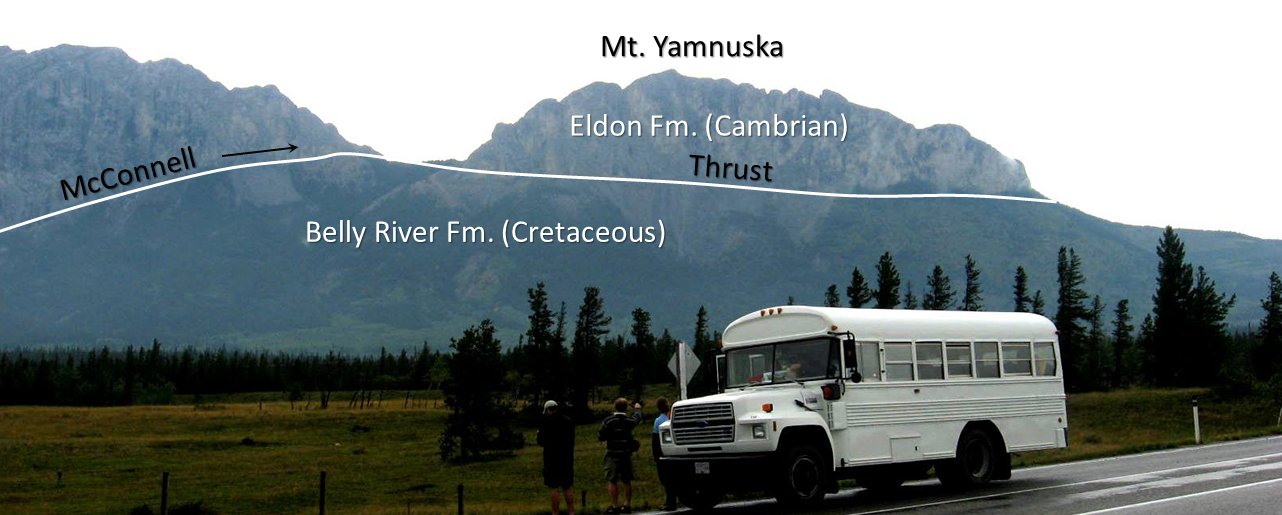
There are numerous thrust faults in the Rocky Mountains, and a well-known example is the McConnell Thrust, along which a sequence of sedimentary rocks about 800 m thick has been pushed for about 40 km from west to east over underlying rock (Figure 13.29). The thrusted rocks range in age from Cambrian to Cretaceous, so in the area around Mt. Yamnuska Cambrian-aged rock (around 500 Ma) has been thrust over, and now lies on top of Cretaceous-aged rock (around 75 Ma) (Figure 13.30).
_](figures/13-geological-structures-and-mountain-building/figure-13-29.png)
Figure 13.29: The McConnell Thrust in the eastern part of the Rockies. The rock within the faded area has been eroded. Source: Steven Earle (2015) CC BY 4.0 view source
_](figures/13-geological-structures-and-mountain-building/figure-13-30.png)
Figure 13.30: The McConnell Thrust at Mt. Yamnuska near Exshaw, Alberta. Cambrian limestones have been thrust over top of Cretaceous mudstone. Source: Steven Earle (2015) CC BY 4.0 view source
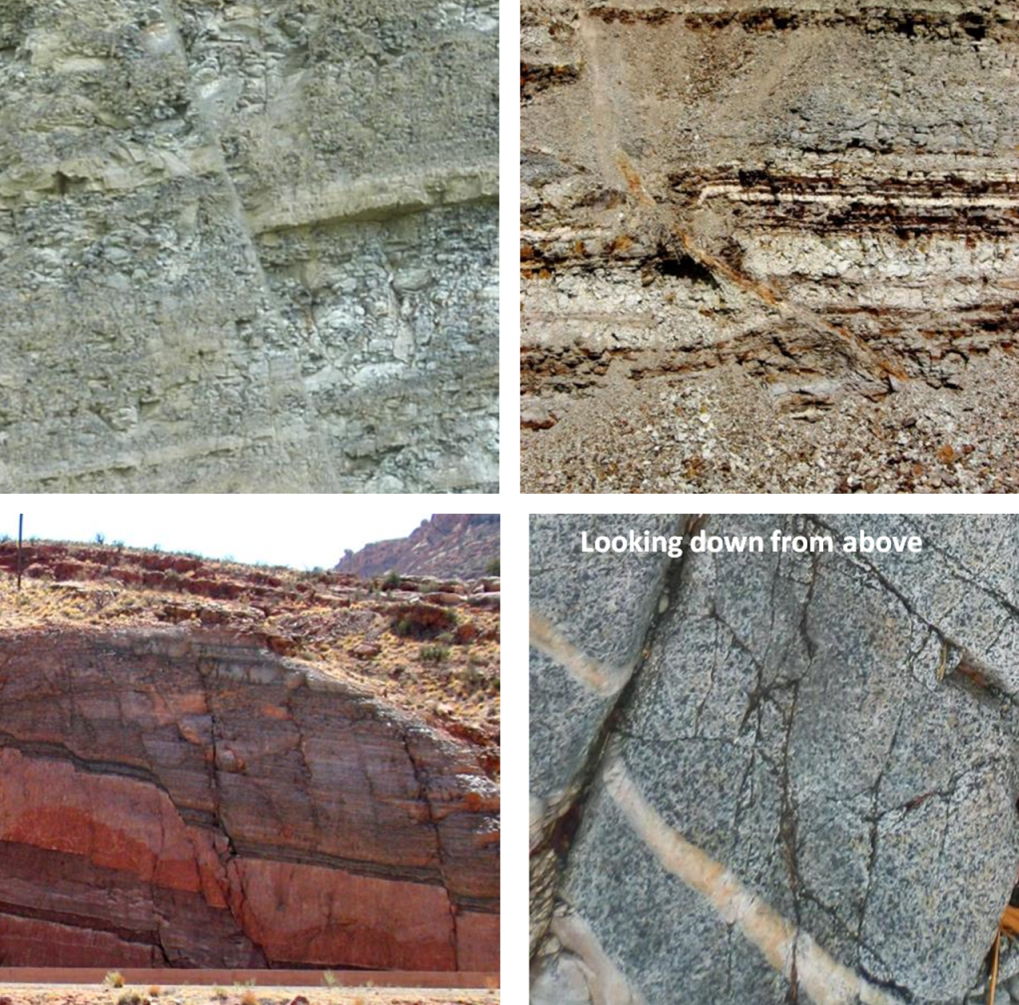
Exercise: Fault Types
_](figures/13-geological-structures-and-mountain-building/figure-13-31.png)
Figure 13.31: A dip-slip fault. Source: Steven Earle (2015) CC BY 4.0 view source
13.4 Mountain Building
Some of Earth’s mountains are entirely or almost entirely the result of volcanic activity. These include volcanic islands like the Hawai’ian hotspot volcanoes, and newly formed volcanic island arcs along subduction zones. But the majority of mountain building on Earth is the result of plate tectonic forces that deform Earth’s crust through faulting and folding. Mountain building through folding and faulting may or may not be supplemented by volcanic activity.
13.4.1 Mountain Building Along Convergent Margins
Mountain building along convergent margins is referred to as orogeny, and the mountains that are built are called orogens.
13.4.1.1 Ocean-Continent Collision
In ocean-continent collision zones, folding and faulting of rocks combines with volcanism to build mountains. An example of mountains built this way is the Sierra Nevada mountain range in Utah and Nevada. The orogeny that formed the Sierra Nevada range began around 140 million years ago.
The mountain range was built up by igneous intrusions and volcanic eruptions along a continental volcanic arc (Figure 13.32). The terrain was altered further inland as well. Sheets of rock were thrust on top of each other, and pushed inland along a detachment fault, similar to the example of the McConnell Thrust in Figure 13.29.
. Click the image for terms of use._](figures/13-geological-structures-and-mountain-building/figure-13-32.png)
Figure 13.32: Orogeny in an ocean-continent collision zone. Mountains form from subduction zone volcanism, and from large sheets of rock that are thrust inland and folded. Materials accumulating on the leading edge of the continent in an accretionary wedge are eventually smashed onto the continent, adding to continental crust. Source: Karla Panchuk (2018) CC BY 4.0. Modified after Ron Blakey, NAU Geology (n.d.) view source. Click the image for terms of use.
Continental crust flexed downward because of the weight of the mountains, and this formed a fore arc basin seaward of the new mountain range. Sediments accumulated within that basin. The leading edge of the continent also collected sediments and igneous rock scraped off the subducting plate, forming an accretionary wedge. Over time, the force of the collision would smash the basin sediments and the accretionary wedge against the continent, turning it into new continental crust.
Continent-Continent Collision
When two continents collide, it means the closure of a subduction zone, and an end to volcanism. The Alleghenian Orogeny, which brought together North America and Africa, helping to form Pangea, is an example of mountain building in a continent-continent collision zone. Before the continents came into contact with each other, mountain building on the eastern coast of North America would have involved deformation from an ocean-continent collision, as with Figure 13.32. But as subduction proceeded, the subducting plate drew Africa closer and closer to North America. The gap between the two continents began to close, and fill with sediments (Figure 13.33, top).
. Click the image for terms of use._](figures/13-geological-structures-and-mountain-building/figure-13-33.png)
Figure 13.33: Orogeny by continent-continent collision. The formation of Pangea included the merging of Africa and North America. This closed an ocean basin and stopped subduction along the coast of North America. Volcanism ended with the closure of the ocean basin, but mountains continued to grow through folding and faulting. Source: Karla Panchuk (2018) CC BY 4.0. Modified after Ron Blakey, NAU Geology (n.d.) view source. Click the image for terms of use.
While a subduction zone existed, the addition of water to the mantle permitted partial melting of mantle rocks, and thus volcanic activity. However, when the two continents collided, the subduction zone closed off and volcanism was no longer possible. As the continents smashed together, deep faults formed and stacked blocks of crust on top of each other. Old faults were reactivated. Rocks also began to shift along the boundary between an earlier orogen, the Taconic Orogen, and North America (Figure 13.33, bottom). When the continents had finally merged, Africa met North America along a suture zone with remnants of a continental volcanic arc on one side, and folded and faulted sedimentary rocks on the other.
13.4.2 Mountain Building Along Divergent Margins
When continents begin to split apart, normal faults form. This can lead to large blocks of crust that are tilted, raised, or lowered compared to adjacent blocks. Blocks that are elevated compared to adjacent blocks can form another type of mountain, called a fault-block mountain. Fault block mountains formed in eastern North America when Pangea began to split up, and Africa pulled away from North America (Figure 13.34).
. Click the image for terms of use._](figures/13-geological-structures-and-mountain-building/figure-13-34.png)
Figure 13.34: Fault-block mountains formed in a rift zone. Magma can move up along normal faults, resulting in igneous intrusions, or volcanic eruptions. Over time, valleys between elevated blocks will fill with sediment as the blocks erode. Source: Karla Panchuk (2018) CC BY 4.0. Modified after Ron Blakey, NAU Geology (n.d.) view source. Click the image for terms of use.
Over time, elevated blocks erode, filling up valleys with sediment. The thinning of continental crust that occurs with rifting can decrease the pressure on mantle rocks enough to trigger partial melting. Magma can move up along the normal faults, forming igneous intrusions, or feeding volcanoes. The Palisades Sill in New York and New Jersey is a result of rift-zone magmatism. It is a cliff-like feature resulting from erosion that exposed the tip of a structure like the sills in Figure 13.34.
13.5 Measuring Geological Structures
Documenting the characteristics of geological structures is used to understand the geological history of a region. One of the key features to measure is the orientation, or attitude, of bedding. We know that sedimentary beds are deposited in horizontal layers, so if the layers are no longer horizontal, then we can infer that tectonic forces have folded or tilted them.
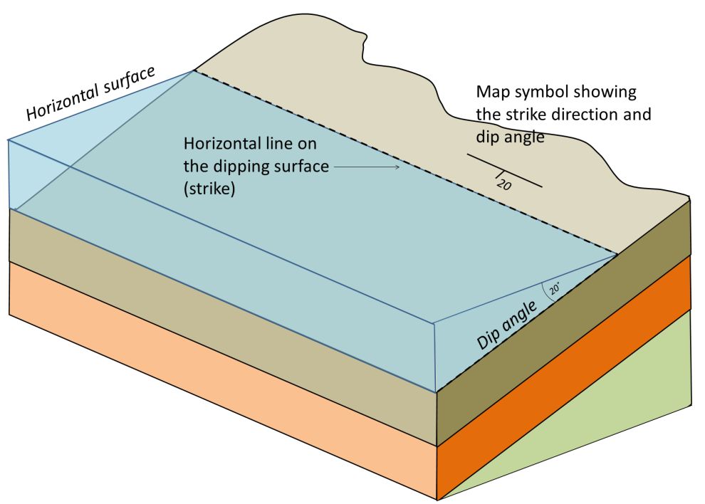
The orientation of a planar feature, such as a bed of sedimentary rock, can be described with two values. The __strike __of the bed is the compass orientation of a horizontal line on the surface of the bed. The __dip __is the angle at which the surface tilts down from the horizontal (Figure 13.35). The dip is measured perpendicular to strike, otherwise the dip angle that is measured will be smaller than the actual tilt of the bed.
_](figures/13-geological-structures-and-mountain-building/figure-13-35.png)
Figure 13.35: Strike and dip for tilted sedimentary beds. Water provides a horizontal surface. The strike and dip symbol is a T with the long horizontal bar representing the strike direction, and the small tick mark indicating the dip direction. The dip angle is written next to the tick mark. Source: Karla Panchuk (2018) CC BY 4.0. Modified after Steven Earle (2015) CC BY 4.0 view source
It may help to imagine a vertical surface, such as a wall in your house. The strike is the compass orientation of the wall and the dip is 90˚ from horizontal. If you could push the wall so it is leaning over, but still attached to the floor, the strike direction would be the same, but the dip angle would be less than 90˚. If you pushed the wall over completely so it was lying on the floor, it would no longer have a strike direction because you could draw a horizontal line in any of an infinite number of directions on the horizontal surface of the wall. Its dip would be 0˚.
When reporting the dip, include the direction. For example, if the strike runs north-south and the dip is 30˚, it would be necessary to specify “to the west” or “to the east.” Similarly if the strike is northeast-southwest and the dip is 60˚, it would be necessary to say “to the northwest” or “to the southeast.” In the case of the vertical wall with a dip angle of 90˚, there is no dip direction. The dip points straight down, not toward any compass direction.
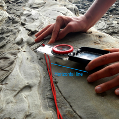
Measurement of geological features is done with a special compass that has a built-in clinometer, which is a device for measuring vertical angles. The strike is measured by aligning the compass along a horizontal line on the surface of the feature (Figure 13.36, left). The dip is measured by turning the compass on its side and aligning it along the dip direction (Figure 13.36, right).
/ [right](http://opentextbc.ca/geology/wp-content/uploads/sites/110/2015/08/figure12.192.png)_](figures/13-geological-structures-and-mountain-building/figure-13-36.png)
Figure 13.36: Measurement of strike (left) and dip (right) using a geological compass with a clinometer. Source: Steven Earle (2015) CC BY 4.0 view source left/ right
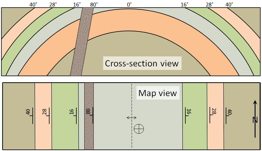
Strike and dip are used to describe any other planar features, including joints, faults, dykes, sills, and even the foliation planes in metamorphic rocks. Figure 13.37 shows an example of how we would depict the beds that make up an anticline on a map. The beds on the west (left) side of the map are dipping at various angles to the west. The beds on the east side are dipping to the east. The beds in the middle are horizontal; this is denoted by a cross within a circle on the map. The dyke is dipping at 80˚ to the west. The hinge line of the fold is denoted with a dashed line on the map, with two arrows pointing away from it, indicating the general dip directions of the limbs. If it were a syncline, the arrows would point inward toward the line.
_](figures/13-geological-structures-and-mountain-building/figure-13-37.png)
Figure 13.37: A depiction of an anticline and a dyke in cross-section (looking from the side) and in map view (or plan view) with the appropriate strike-dip and anticline symbols. Source: Steven Earle (2015) CC BY 4.0 view source
Exercise: Putting Strike and Dip on a Map
This cross-section shows seven tilted sedimentary layers (a to g), a fault, and a steeply dipping dyke.
_](figures/13-geological-structures-and-mountain-building/figure-13-38.png)
Figure 13.38: Practice with strike and dip symbols. Source: Steven Earle (2015) CC BY 4.0 view source
- Place strike and dip symbols on the map to indicate the orientations of the beds shown, the fault, and the dyke.
- What type of fault is shown?
- What kind of stress created the fault?
13.6 Summary
The topics covered in this chapter can be summarized as follows:
13.6.1 Stress and Strain
Stress within rocks, which includes compression, extension and shearing, originates from plate tectonic processes and the weight of overlying rocks. Rock that is stressed responds with either elastic or plastic strain, and may eventually break. The way a rock responds to stress depends on its composition and structure, the rate at which strain is applied, and also on the temperature, pressure, and the presence of fluid within the rock.
13.6.2 Folding
Folding is generally a ductile response to compression, although some brittle behaviour can happen during folding. A fold with a hinge that points upward is an anticline. A fold with a hinge that points downward is a syncline. The axial surface of a fold can be vertical, inclined, or even horizontal. The landforms produced by folds will depend on the resistance to weathering of rock layers within the fold.
13.6.3 Fractures, Joints, and Faults
Joints typically form during extension, but can also form during compression. Faulting, which involves the displacement of rock, can take place during compression or extension, as well as during shearing at transform boundaries. Thrust faults are a type of reverse fault with a fault plane tilted at a low angle. Thrust faults are common in mountain belts formed by plate collisions.
13.6.4 Mountain Building
Mountain building in zones of plate collision is called orogeny. The mountains that form are orogens, and consist of crust thickened and deformed by folding and faulting, as well as the intrusion of igneous rocks. Orogens in ocean-continent collision zones have volcanoes. Mountains formed in rift zones are the result of tilting of normal-faulted blocks, or some normal-faulted blocks subsiding while others remain elevated.
13.6.5 Measuring Geological Structures
The strike and dip of planar surfaces, such as a bedding planes, fractures or faults are measured to help understand the geological history of a region. Special symbols are used to show the orientation of structural features on geological maps.
13.7 Chapter Review Questions
What types of plate boundaries are most likely to contribute to (a) compression, (b) extension, and (c) shearing?
Explain the difference between elastic strain and plastic strain.
List some of the factors that influence whether a rock will undergo ductile deformation or break when placed under stress.
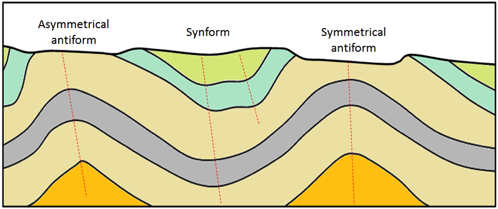
Draw in the axial traces of the folds in Figure 13.39, and label each with the appropriate type (e.g., overturned syncline).
_](figures/13-geological-structures-and-mountain-building/figure-13-39.png)
Figure 13.39: A cross-section showing folds. Source: Steven Earle (2015) CC BY 4.0 view source
Explain why fractures are common in volcanic rocks.
What is the difference between a normal fault and a reverse fault, and under what circumstances would you expect these to form?
What type of fault would you expect to see at a transform plate boundary?
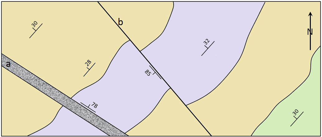
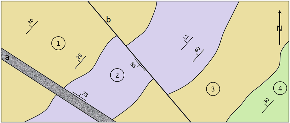
Figure 13.40 is a map of the geology of a region. The coloured areas represent sedimentary beds.
- Describe in words the general attitude (strike and dip) of these beds.
- What is “a” and what is its attitude?
- What is “b” and what is its attitude?
- Is “b” left handed or right handed?
_](figures/13-geological-structures-and-mountain-building/figure-13-40.png)
Figure 13.40: Geological map. Source: Steven Earle (2015) CC BY 4.0 view source
13.8 Answers to Chapter Review Questions
Convergent plate boundaries are the most likely to contribute to compression, divergent boundaries to extension, and transform boundaries to shearing. However, all of these stress regimes can exist at any one of these boundaries.
When elastic strain takes place the rock can rebound to its original shape when stress is removed. Plastic strain is permanent.
Ductile deformation is more likely under higher temperatures and confining pressures. It is more likely when rocks are deformed slowly, and by compression. It is more likely for sedimentary rocks, and for rocks without fluids.
Axial traces are shown with dashed red lines.
_](figures/13-geological-structures-and-mountain-building/figure-13-41.png)
Figure 13.41: Folds with labels. Source: Steven Earle (2015) CC BY 4.0 view source
Volcanic rocks cool quickly at surface and the resulting reduction in volume can easily lead to fracturing.
In a normal fault the rock above the fault (hanging wall or headwall) moves down with respect to the lower rock (footwall). This normally indicates extension. In a reverse fault the hanging wall is pushed up, which indicates compression.
Most faults near transform boundaries are strike-slip faults, meaning that there is horizontal motion along the fault.
- The beds are dipping at about 30˚ to the northwest. (ii) “a” is a dyke and it is dipping steeply to the northeast. (iii) “b” is a fault and it is dipping steeply to the southeast. (iv) The motion on fault “b” appears to be left handed.
_](figures/13-geological-structures-and-mountain-building/figure-13-42.png)
Figure 13.42: Geological map with strike and dip symbols. Source: Steven Earle (2015) CC BY 4.0 view source
13.9 References
Heard, H. C. (1960). Transition from Brittle Fracture to Ductile Flow in Solenhofen Limestone as a Function of Temperature, Confining Pressure, and Interstitial Fluid Pressure. In D. Griggs & D. Handin (Eds.), Rock Deformation (A Symposium): Geological Society of America Memoir 79 (pp. 193-226). https://doi.org/10.1130/MEM79
Symonds, W. S. (1872). Records of the rocks; or, Notes on the geology, natural history, and antiquities of North & South Wales, Devon, & Cornwall. London: J. Murray Read the book