Chapter 15 Mass Wasting
Adapted from Physical Geology, First University of Saskatchewan Edition (Joyce M. McBeth) and Physical Geology (Steven Earle)
Learning Objectives
After reading this chapter, completing the exercises within it, and answering the questions at the end, you should be able to:
- Explain how slope stability is related to slope angle
- Summarize some of the factors that influence the strength of materials on slopes, including the type of rock, the presence and orientation of planes of weakness such as bedding planes or fractures, the type of unconsolidated material upon the slope, and the effects of water flowing upon or within the slope material
- Explain what types of events can trigger mass wasting
- Summarize the types of motion that can happen during mass wasting
- Describe the difference between a translational and a rotational slope failure
- Describe the main types of mass wasting — creep, slump, slide, fall, and debris or mud flow — in terms of the types of materials involved, the type of motion, and the likely rates of motion
- Explain what steps we can take to delay mass wasting, and why we cannot prevent it permanently
- Describe some of the measures that can be taken to mitigate the risks associated with mass wasting
Mass wasting is the failure and downslope movement of rock or unconsolidated materials in response to gravity. Mass wasting is an agent of erosion. The term “landslide” is used synonymously with the term mass wasting, but they are not the same thing. Some people reserve the term “landslide” for relatively rapid slope failures, while others do not. Due to this ambiguity, we avoid the use of the term “landslide” in this textbook.
15.0.1 The Hope Slide: a Historic Canadian Example of a Mass Wasting Event
Early in the morning of January 9, 1965, 47 million cubic metres of rock broke away from the steep upper slopes of Johnson Peak (16 km southeast of Hope, B.C.) and tumbled 2,000 m down the mountain, gouging out the contents of a small lake at the bottom, and continuing a few hundred metres up the other side of the valley (Figure 15.1). Four people were killed who had been stopped on the highway by a snow avalanche. Many more people might have become victims, except that a Greyhound bus driver, en route to Vancouver, turned his bus around upon seeing the avalanche. The rock failed along foliation planes of the metamorphic rock on Johnson Peak, in an area that had been eroded into a steep slope by glacial ice. There is no evidence that it was triggered by any specific event, and there was no warning that it was about to happen. Even if there had been warning, nothing could have been done to prevent it. There are hundreds of similar sites throughout mountainous regions of British Columbia and elsewhere in Canada where large mass wasting events could occur.
](figures/15-mass-wasting/figure-15-1.jpg)
Figure 15.1: | The site of the 1965 Hope Slide, photographed in 2014. The initial failure is thought to have taken place along foliation planes in the rock and a sill. Source: Wikimedia Commons. View Source
What can we learn from the Hope Slide? In general, we cannot prevent most mass wasting events, and significant effort is required if an event is to be predicted with any level of certainty. Understanding the geology is critical to understanding mass wasting. Although slope failures are inevitable in a region with steep slopes, larger slope failures happen less frequently than smaller ones. The consequences of a large mass wasting event also vary depending on the downslope conditions, such as the presence of people, buildings, roads, or fish-bearing streams.
An important reason for learning about mass wasting is to understand the nature of how and why materials fail in mass wasting events. If we understand this better, we can use this knowledge to help minimize the risks from similar events in the future.
15.1 Factors That Control Slope Stability
15.1.1 Slope Angle and the Forces Acting On A Slope
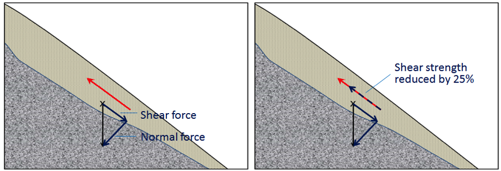
A block of rock situated on a rock slope is pulled by gravity toward Earth’s centre (vertically down, Figure 15.2). We can split the vertical gravitational force into two components (vectors) relative to the slope: one pulling the block down parallel to the slope (the shear force), and the other pulling the block directly into (i.e., perpendicular) to the slope (the normal force).
The shear force pulls the block down the slope, but the block does not move unless the shear force overcomes (is greater than) the friction between the block and the slope. This friction holding the block on the slope may be quite weak if the block has split away from the main body of rock, or may be very strong if the block is still connected to the other rock on the slope. The strength of the relationship between the block and the slope is called the shear strength. For example, in Figure 15.2a, the shear strength is greater than the shear force, so the block will not move. In Figure 15.2b the slope is steeper, and the shear force is approximately equal to the shear strength. The block may or may not move under these circumstances. In Figure 15.2c, the slope is steeper still, so the shear force is considerably greater than the shear strength, and the block will move.
_](figures/15-mass-wasting/figure-15-2.png)
Figure 15.2: | Differences in the shear and normal components of the gravitational force on slopes with differing steepness. The total gravitational force is the same in all three cases. In (a) the shear force (red line aligned with slope) is substantially less than the shear strength (green arrow), so the block is stable. In (b) the shear force and shear strength are nearly equal, so the block may or may not move. In (c) the shear force is greater than the shear strength, so the block will move. Source: Steven Earle (2015) CC BY 4.0. view source
Slopes are created by uplift in the Earth’s crust and modified by erosion. In areas with relatively recent uplift (such as most of British Columbia and the western part of Alberta in Canada), slopes tend to be quite steep. This is especially true where glaciation has taken place because glaciers in mountainous terrain create steep-sided U-shaped valleys. In areas without recent uplift (such as central Canada), slopes are less steep because they have been subjected to erosion, including mass wasting, for long periods of time. Note that mass wasting can happen even on relatively gentle slopes if the shear stress acting on the materials is greater than the materials’ shear strength.
15.1.2 Slope Strength
The strength of the materials on slopes can vary widely. Solid rocks tend to be strong, but rock strength varies widely, so this is not always the case. If we consider just the strength of the rocks and ignore issues such as fracturing and layering, then most crystalline rocks (e.g., granite, basalt, or gneiss) are very strong, while some metamorphic rocks (e.g., schist) are only moderately strong. Sedimentary rocks have variable strength. Dolostone and some limestone are strong, most sandstone and conglomerate are moderately strong, and some sandstone and all mudstones are quite weak.
Fractures, metamorphic foliation (excluding gneissosity and banding), or bedding can significantly reduce the strength of rock. In the context of mass wasting, this is most critical if the planes of weakness are parallel to the slope and least critical if they are perpendicular to the slope. This is illustrated in Figure 15.3 At locations A and B the bedding is nearly perpendicular to the slope and the layers of rock are relatively stable. At location D the bedding is nearly parallel to the slope and the layers of rock are relatively unstable. At location C the bedding is nearly horizontal, and the stability is intermediate between the two extremes.
 _](figures/15-mass-wasting/figure-15-3.png)
Figure 15.3: | Relative stability of slopes. The stability is as a function of the orientation of planes of weakness (in this case bedding planes) relative to the slope orientations. Source: Steven Earle (2015) CC BY 4.0. View source
Internal variations in the composition and structure of rocks can significantly affect their strength. Schist, for example, may have layers that are rich in sheet silicates (micas) and these will tend to form weak layers. Some minerals tend to be more susceptible to weathering than others, and the weathered products are commonly quite weak (e.g., clay formed from feldspar). The side of Johnson Peak that failed in 1965 (Hope Slide) is made up of chlorite schist (metamorphosed sea-floor basalt) that has feldspar-bearing sills within it. The foliation and the sills are parallel to the steep slope. The schist is relatively weak to begin with, and the feldspar in the sills, which has been altered to clay, makes it even weaker.
Unconsolidated sediments are generally weaker than sedimentary rocks because they are not cemented and, in most cases, have not been significantly compressed by overlying materials. Unconsolidated sediments can still bind together, and the strength of that binding is called cohesion. A cohesive sediment binds together strongly and if you picked it up with a shovel it would stick together in a lump (e.g., sand mixed with clay, clay). A sediment that is not very cohesive is weakly bound and would probably fall apart if you picked it up with a shovel (e.g., sand, silt). The deposits that make up the cliffs at Point Grey, Vancouver, B.C. include sand, silt, and clay, overlain by sand. The finer deposits at Point Grey are relatively cohesive (they maintain a steep slope, Figure 15.4 left). The overlying sand is not very cohesive (relatively weak) and has a shallower slope because there are many slope failures in the sand deposit.
_](figures/15-mass-wasting/figure-15-4.png)
Figure 15.4: Left: Glacial outwash deposits at Point Grey, Vancouver, B.C. The dark lower layer is made up of sand, silt, and clay. The light upper layer is well-sorted sand, which has experienced slope failure and formed a cone of talus. Right: Glacial till on Quadra Island, B.C. The till is strong enough to have formed a near-vertical slope. Source: Steven Earle (2015) CC BY 4.0. View source
In contrast to poorly cohesive sediment deposits, glacial till can be as strong as some sedimentary rock. Glacial till is typically a mixture of clay, silt, sand, gravel, and larger clasts and forms and is compressed beneath tens to thousands of metres of glacial ice (Figure 15.4, right).
Apart from the type of material on a slope, the amount of water that the material contains is the most important factor controlling its strength. This is especially true for unconsolidated materials (e.g., Figure 15.4), but it also applies to bodies of rock. Granular sediments, like the sand at Point Grey, have lots of pore spaces between the grains. These spaces may be completely dry (filled only with air), moist (some spaces are water filled), or completely saturated (Figure 15.5).
Unconsolidated sediments tend to be strongest when they are moist because the small amounts of water at grain boundaries holds the grains together due to surface tension. Surface tension is the tension at the surface of a fluid that allows the liquid to resist an external force. Liquids always tend to acquire the lowest surface area possible; this happens because molecules at the surface of the fluid are attracted to the molecules below the surface). This is the property of liquid water that allows insects to walk over it. Dry sediments are held together only by the friction between grains, and if they are well sorted or well rounded, or both, this cohesion is weak, due to minimal grain contact. Saturated sediments tend to be the weakest of all because the water pushes the grains apart, decreasing friction between grains. Water will also reduce the strength of solid rock, if the rock has porosity, fractures, bedding planes, and/or clay-bearing zones, especially when the rock is saturated with water (saturated conditions).
 _](figures/15-mass-wasting/figure-15-5.png)
Figure 15.5: | Depiction of dry, moist, and saturated sand. Source: Steven Earle (2015) CC BY 4.0. View source
Water pressure is an important factor in slope failure. As you move deeper in saturated sediment, the pressure of the water goes up due to gravity acting on the column of water above it; this pressure is called hydrostatic pressure. The greater the depth below the surface of the water table (the point where the rock or sediments are saturated), the greater the water pressure acting on the materials. Holes are often drilled into rocks in road cuts to allow water to drain and relieve this water pressure. One of the hypotheses advanced to explain the 1965 Hope Slide is that cold conditions that winter caused small springs in the lower part of the slope to freeze, preventing water from flowing out. It is possible that water pressure gradually built up within the slope, weakening the rock mass to the extent that the shear strength was no longer greater than the shear force.
Water also has an interesting effect on clay-bearing materials. All clay minerals will absorb a small quantity of water, which reduces the strength of the clay. The smectite clays (such as the bentonite used in cat litter) can absorb a lot of water, and this water pushes the clay sheets apart at a molecular level, which makes the clay swell. Smectite that has expanded in this way has almost no strength; it is extremely slippery. Thus, slopes containing smectite clay are more likely to experience slope failure when they are saturated.
Water can increase the mass of the material on a slope, because the mass of the water is a component of the overall mass of the slope material. This increases the gravitational force pulling the slope materials down. A water saturated body of sediment with 25% porosity weighs approximately 13% more than it does when it is completely dry, so the gravitational shear force is also 13% higher. In the situation shown in Figure 15.2b, a 13% increase in the shear force is enough to overcome the shear strength, and the block would move down the slope.
Exercise: Sand and Water
Source: Steven Earle (2015) CC BY 4.0.View source
If you have ever been to the beach, you already know that sand behaves differently when it is dry than it does when it is wet. The following experiment will demonstrate the strength of sand when it is dry, moist and saturated.
Find approximately half a cup of clean, dry sand (or get some wet sand and dry it out), and then pour it from your hand onto a piece of paper. You should be able to make a cone-shaped pile that has a slope of ~30°. If you pour more sand onto the pile, it will get bigger, but the slope should remain the same.
Now add some water to the sand so that it is moist. One way to do this is to add enough water to saturate the sand, then let the water drain away for a minute. You should be able to form this moist sand into a steep pile (with slopes of ~80°).
Finally, put some sand into a cup and fill the cup with water so the sand is just covered. Swirl it around so that the sand remains in suspension, and then quickly tip it out onto a flat surface. It should spread out over a wide area, forming a pile with a slope of only a few degrees.
15.1.3 Triggers of Mass-Wasting
In the previous section, we discussed the shear force and the shear strength of materials on slopes, and factors that can decrease the shear strength. Shear force is primarily related to slope angle, and once a slope angle is set, the shear force is constant. But shear strength can change quickly for a variety of reasons. Events that lead to a rapid decrease in shear strength are triggers for mass wasting.
An increase in water content is the most common trigger of mass wasting. This can result from rapid melting of snow or ice, heavy rain, or other events that change the pattern of water flow on and through the material. Rapid melting can be caused by a dramatic increase in temperature (e.g., in spring or early summer), or by a volcanic eruption. Heavy rains are typically related to storms. An example of a major slope failure caused by an increase in water content was the Oso landslide that occurred in Washington State, USA in 2014 (Figure 15.6). The flow buried the community of Steelhead Haven and killed 43 people.
](figures/15-mass-wasting/figure-15-6.jpg)
Figure 15.6: | The Oso landslide, a flow that occurred in Washington State, USA 22 March 2014. Source: Matthew Sissel (2014) Public Domain. View source
Changes in water flow patterns can be caused by earthquakes, dammed streams from previous slope, or human structures that interfere with runoff (e.g., buildings, roads, or parking lots). An example of this is a deadly 2005 debris flow in North Vancouver, B.C. This slope failure took place in an area where there had been previous slope failures. A report written in 1980 recommended that the municipal authorities and residents take steps to address surface and slope drainage issues. Unfortunately, little was done to improve the situation or to take steps that could have prevented the 2005 slope failure. The failure happened during a rainy period but was likely triggered by excess runoff related to the roads at the top of this slope and by landscape features including addition of fill to backyards in the area above the failure.
In some cases, a decrease in water content can lead to failure. This is most common with clean sand deposits (e.g., the upper layer in Figure 15.4 (left)), which loses some of its strength when most of the water around the grains is removed (i.e., as the sand water content drops the surface tension decreases).
Freezing and thawing can also trigger some forms of mass wasting e.g., thawing can release a block of rock that was frozen to a slope by a film of ice.
One other process that can weaken a body of rock or sediment is shaking. The most obvious source of shaking is an earthquake. Shaking from highway traffic, construction, or mining can also weaken rock. Several deadly mass wasting events (including snow avalanches) were triggered by the M7.8 earthquake in Nepal in April 2015.
15.2 Classification of Mass Wasting
- There are three criteria used to classify slope failures:
- The type of material that failed (e.g., bedrock or unconsolidated sediment),
- The mechanism of the failure (how the material moved as it failed), and
- The rate of movement (how quickly the material moved).
- The mechanism of the failure is the most important characteristic of a slope failure. There are three main mechanisms of slope failure:
- Fall: in falls, the material falls through the air, either vertically or nearly vertically,
- Slide: in slides, the material moves as a coherent mass along a sloping surface (with little to no internal motion within the mass), and
- Flow: in flows the failing material has internal motion (like a fluid) as it moves.
While we do not classify slope failures by the shape of the rupture surface, it is nevertheless an important feature used to describe mass wasting processes. The rupture surface is the boundary between the slope and the sliding material. Slope failures with curved rupture surfaces are called rotational slope failures, and slope failures with planar rupture surfaces are called translational slope failures.
Unfortunately, classifying slope failure is not as simple as the classification scheme above suggests__.__ Many slope failures involve more than one type of motion, and often it is not easy to tell how the material moved. The types of slope failure that are covered in this chapter are summarized in Table 15.1.
| Failure Type | Type of Material | Type of Motion | Rate of Motion |
|---|---|---|---|
| Rock fall | Rock fragments | Vertical or near-vertical fall (plus bouncing in many cases) | Very fast (>10s m/s) |
| Rock slide | A large rock body | Motion as a unit along a planar surface (translational sliding) | Typically very slow (mm/y to cm/y), but some can be faster |
| Rock avalanche | A large rock body that slides and then breaks into small fragments | Flow (at high speeds, the mass of rock fragments is suspended on a cushion of air) | Very fast (>10s m/s) |
| Creep or solifluction | Soil or other overburden; in some cases, mixed with ice | Flow (although sliding motion may also occur) | Very slow (mm/y to cm/y) |
| Slump | Thick deposits (m to 10s of m) of unconsolidated sediment | Motion as a unit along a curved surface (rotational sliding) | Slow (cm/y to m/y) |
| Mudflow | Loose sediment with a significant component of silt and clay | Flow (a mixture of sediment and water moves down a channel) | Moderate to fast (cm/s to m/s) |
| Debris flow | Sand, gravel, and larger fragments | Flow (similar to a mudflow, but typically faster) | Fast (m/s) |
15.2.1 Rock Fall
Rock fragments can break off relatively easily from steep bedrock slopes, most commonly due to frost-wedging. If you ever hike along a steep mountain trail on a cool morning, you will probably hear the occasional fall of rock fragments onto a talus slope. Water in the cracks in the rock freezes and expands overnight, and this can break the rock apart. When the ice thaws in the morning sun, some of these broken fragments will fall to the slope below (Figure 15.7). Talus slopes form from this fallen rock, forming slopes at the angle of repose below high rock walls (Figure 15.8, left). They are also known as scree slopes.
 _](figures/15-mass-wasting/figure-15-7.png)
Figure 15.7: | The contribution of freeze-thaw to a rock fall. Source: Steven Earle (2015) CC BY 4.0. View source
A typical talus slope, near Keremeos in southern BC, is shown in Figure 15.8. In December 2014, a large block of rock split away from a cliff in this same area. It broke into smaller pieces that tumbled down the slope and crashed into the road, smashing the concrete barriers and gouging out large parts of the pavement. Luckily no one was hurt.
 _](figures/15-mass-wasting/figure-15-8.png)
Figure 15.8: | Left: A talus slope near Keremeos, B.C., formed by rock falls from the cliffs above. Right: The results of a rock fall onto a highway west of Keremeos in December 2014. Source: Steven Earle (2015) CC BY 4.0. View source
15.2.2 Rock Slide
A rock slide is a large body of rock that is sliding along a sloping surface. In most cases, the movement is parallel to a fracture, bedding plane, or metamorphic foliation plane; thus, most rock slides are translational slope failures.
The speed of the movement can range from very slow to moderately fast. The word sackung describes the very slow motion of a block of rock (mm/y to cm/y) on a slope. A good example is the Downie Slide, a translational slide north of Revelstoke, BC, which is shown in Figure 15.9. In this case, a massive body of rock is very slowly sliding down a steep slope along a plane of weakness that is caused by the foliation in the rock. The foliation is approximately parallel to the slope.
The Downie Slide was recognized prior to the construction of the Revelstoke Dam, and was moving very slowly at the time of dam construction (a few cm/year). Geological engineers were concerned that the presence of water in the reservoir (visible in Figure 15.9) could further weaken the plane of failure, leading to an acceleration of the motion. The result would have been a catastrophic failure into the reservoir that would have sent a wall of water over the dam and into the community of Revelstoke.
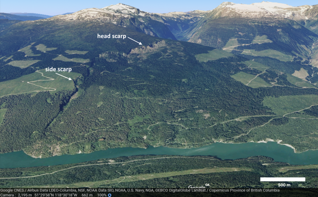
Figure 15.9: | The Downie Slide, a sackung, on the shore of the Revelstoke Reservoir (above the Revelstoke Dam). The head scarp is visible at the top and a side-scarp along the left side. Source: Joyce McBeth (2018) CC BY 4.0, image © 2018 Google Earth, Data Google CNES / Airbus Data LDEO-Columbia, NSF, NOAA Data SIO, NOAA, U.S. Navy, NGA, GEBCO DigitalGlobe Landsat / Copernicus Province of BC.
During the construction of the dam, the engineers tunnelled into the rock at the base of the slide and drilled hundreds of drainage holes upward into the plane of failure. This allowed water to drain out more efficiently so that the hydrostatic pressure was decreased, which decreased the rate of movement of the sliding block. BC Hydro monitors this site continuously. The slide block is currently moving more slowly than it was prior to the construction of the dam.
In the summer of 2008, a large block of rock slid rapidly from a steep slope above Highway 99 near Porteau Cove, BC (between Horseshoe Bay and Squamish). The block crashed into the highway and adjacent railway and broke into many pieces, and the highway was closed for several days. Engineers and geoscientists took steps to stabilize the slope to decrease the risk of future rock falls. Rock bolts (long metal rods) were installed to anchor the blocks of rocks and prevent them falling Drainage holes were installed to drain water from the slope and decrease the water pressure. As shown in Figure 15.10, the rock along the slope is fractured parallel to the slope, and this almost certainly contributed to the failure. However, it is not actually known what triggered this event as the weather was dry and warm during the preceding weeks, and there was no significant earthquake in the region.
](figures/15-mass-wasting/figure-15-10.png)
Figure 15.10: Site of the 2008 rock slide at Porteau Cove. Notice the prominent fracture set parallel to the surface of the slope. The slope has been stabilized with rock bolts (top arrow) and holes have been drilled into the rock to improve drainage (tube from drainage hole indicated with bottom arrow). Risk to passing vehicles from rock fall has been reduced by hanging mesh curtains (background), which secures loose material to the slope. Source: Joyce McBeth (2018) CC BY 4.0 after Steven Earle (2015) CC BY 4.0. View source
15.2.3 Rock Avalanche
If a rock slides and then starts moving quickly (m/s), the rock is likely to break into many small pieces. At this point it is considered to be a rock avalanche, in which the large and small fragments of rock move in a fluid manner supported by a cushion of air within and beneath the moving mass. The 1965 Hope Slide (Figure 15.1) was a rock avalanche, as was the famous 1903 Frank Slide in southwestern Alberta. The 2010 slide at Mt. Meager (west of Lillooet) was also a rock avalanche and rivals the Hope Slide as the largest slope failure in Canada during historical times (Figure 15.11).
](figures/15-mass-wasting/figure-15-11.png)
Figure 15.11: | The 2010 Mt. Meager landslide, showing where the slide originated (arrow, 4 km upstream). It then raced down a steep narrow valley and out into the wider valley in the foreground. Source: Mika McKinnon (2011) CC BY-SA-NC, View source
15.2.4 Creep or Solifluction
The very slow — mm/y to cm/y — movement of soil or other unconsolidated material down slope is known as creep. Creep, which normally only affects the upper several centimetres of loose material, is typically a type of very slow flow. In some cases, sliding may take place too.
Creep can be facilitated by freezing and thawing because, as shown in Figure 15.12, particles are lifted perpendicular to the surface by the growth of ice crystals within the soil, and then move downwards vertically due to gravity when the ice melts. The same effect can be produced by frequent wetting and drying of the soil. In cold environments,__ solifluction__ is a more intense form of freeze-thaw-triggered creep.
 _](figures/15-mass-wasting/figure-15-12.png)
Figure 15.12: | A depiction of the contribution of freeze-thaw to creep. The blue arrows represent uplift caused by freezing in the wet soil underneath, while the red arrows represent depression by gravity during thawing. The uplift is perpendicular to the slope, while the drop is vertical. Source: Steven Earle (2015) CC BY 4.0. View source
Creep is most noticeable on moderate-to-steep slopes where trees or fence posts are consistently leaning in a downhill direction. In the case of trees, they try to correct their lean by growing upright, and this leads to a curved lower trunk known as a “pistol butt.” Creep can also generate terracettes, horizontal and repeating ridges on slopes (Figure 15.13). Historically, people thought terracettes formed where livestock or wild animals regularly travelled along slopes. While animals can accentuate terracettes, the primary reason terracettes form is creep.
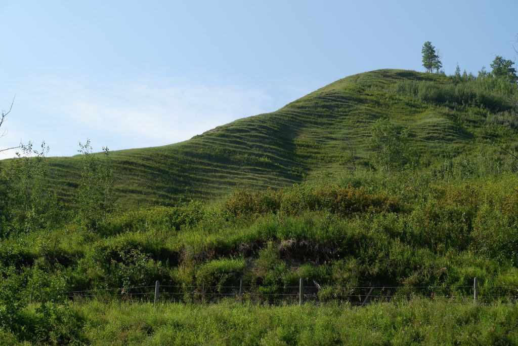
Figure 15.13: | Evidence of creep-generated terracettes on the Peace River hills in northeastern B.C. Source: Joyce McBeth (2018) CC BY 4.0.
15.2.5 Slump
A slide is a mass movement where the material moves as a coherent mass. A slump is a type of slide that takes place within thick unconsolidated deposits (typically thicker than 10 m). Slumps involve movement along one or more curved failure surfaces, and are thus rotational slope failures. Slumps have downward motion near the top and outward motion toward the bottom (Figure 15.14). They are typically caused by high water pressure within these materials on a steep slope.
 _](figures/15-mass-wasting/figure-15-14.png)
Figure 15.14: | The motion of unconsolidated sediments in an area of slumping. _ Source: Steven Earle (2015) CC BY 4.0. View source _
An example of a slump in the Lethbridge area of Alberta is shown in Figure 15.15. This feature has likely been active for many decades and moves a little more whenever there are heavy spring rains and snowmelt runoff. The toe of the slump is being eroded by the small stream at the bottom. The erosion contributes to continued slumping. The basal material (material at the toe of the slope) forms the support for the overlying mass of material in the slope and if this support is eroded away slumping will likely continue.
 _](figures/15-mass-wasting/figure-15-15.jpg)
Figure 15.15: A slump along the banks of a small coulee near Lethbridge, Alberta. The main head-scarp is clearly visible at the top, and a second smaller one is visible about a quarter of the way down the slope. The toe of the slump is being eroded by the seasonal stream that created the coulee. Source: Steven Earle (2015) CC BY 4.0. View source
15.2.6 Mudflows and Debris Flows
As you saw in Exercise 15.1, when a mass of sediment becomes completely saturated with water, the mass loses strength, to the extent that the grains may be pushed apart and may flow, even on a gentle slope. This can happen during rapid spring snowmelt or heavy rains and is also relatively common during volcanic eruptions because of rapid melting of snow and ice. If the material involved is primarily sand-sized or smaller, it is known as a mudflow, such as the one shown in Figure 15.16. A mudflow or debris flow on a volcano or during a volcanic eruption is called a lahar.
If the material involved is gravel sized or larger, it is known as a debris flow. Since it takes more gravitational force to overcome friction and move larger particles, debris flows typically form in areas with steeper slopes and higher water pressure. In many cases, a debris flow takes place within a steep stream channel and is triggered by the collapse of bank material into the stream. This may create a temporary dam followed by a major flow of water and debris when the dam finally bursts. This is the situation that led to the fatal debris flow at Johnsons Landing, BC, in 2012.
<br>_](figures/15-mass-wasting/figure-15-16.png)
Figure 15.16: | A slump (left) and an associated mudflow (centre) at the same location as Figure 15.15, near Lethbridge, Alberta. Source: Steven Earle (2015) CC BY 4.0. View source
A typical west-coast debris flow is shown in Figure 15.17. This event took place in November 2006 in response to very heavy rainfall. There was enough energy in the flow to move large boulders and to knock over large trees.
 _](figures/15-mass-wasting/figure-15-17.png)
Figure 15.17: The lower part of debris flow within a steep stream channel near Buttle Lake, B.C., in November 2006. Note the trees along the edges of the stream that have been damaged by the rocks in the debris flow. Source: Steven Earle (2015) CC BY 4.0. View source
Exercise: Classifying Slope Failures
These four photos show some of the different types of slope failures described above. Try to identify each and provide some criteria to support your choice.
_](https://openpress.usask.ca/app/uploads/sites/29/2017/05/Classifying-Slope-Failures1.jpg)
Figure 15.18: Source of images: Steven Earle (2015) CC BY 4.0. View source
_](https://openpress.usask.ca/app/uploads/sites/29/2017/05/Classifying-Slope-Failures2.jpg)
Figure 15.19: Source of images: Steven Earle (2015) CC BY 4.0. View source
_](https://openpress.usask.ca/app/uploads/sites/29/2017/05/Classifying-Slope-Failures3.jpg)
Figure 15.20: Source of images: Steven Earle (2015) CC BY 4.0. View source
_](https://openpress.usask.ca/app/uploads/sites/29/2017/05/Classifying-Slope-Failures4.jpg)
Figure 15.21: Source of images: Steven Earle (2015) CC BY 4.0. View source
15.3 Preventing, Delaying, Monitoring, and Mitigating Mass Wasting
We cannot prevent mass wasting, however, in many situations there are actions we can take to reduce or mitigate the damaging effects of mass wasting on people and infrastructure. Where we can neither delay nor mitigate mass wasting, we may consider trying to initiate the slope failure in a controlled manner. In areas prone to mass wasting that cannot be controlled or mitigated, we can minimize risk by not building in these areas at all.
15.3.1 Preventing and Delaying Mass Wasting
It is comforting to think that we can prevent some effects of mass wasting by mechanical means. For example, the rock bolts in the road cut at Porteau Cove on the Sea-toSky highway in BC (Figure 15.10) or the drill holes used to drain water out of the slope at the Downie Slide (Figure 15.9), or the building of physical barriers, such as retaining walls along highway roadcuts. These preventative measures are not permanent though, they are subject to degradation over time. The rock bolts in the road cut at Porteau Cove will slowly start to corrode after a few years, and within a few decades many of them will begin to lose their strength. Unless they are replaced, they will no longer support the slope. Likewise, drainage holes at the Downie Slide will eventually become plugged with sediment and chemical precipitates, and unless they are periodically unplugged, their effectiveness will decrease. Eventually, unless new holes are drilled, the drainage will be compromised, and the slide will start to move again. This is why careful slope monitoring by geological and geotechnical engineers is important at major mass wasting sites such as the Downie Slide and along the Sea-to-Sky highway. Our efforts to control mass wasting are only as good as our efforts to maintain the preventive measures.
Delaying mass wasting is a worthy endeavour because during the time that the measures are still effective, they can save lives and reduce damage to property and infrastructure such as homes and roads. But we must be careful to avoid activities that could make mass wasting more likely. One of the most common anthropogenic causes of mass wasting is road construction, and this applies both to remote gravel roads built for forestry and mining, and large urban and regional highways.
 _](figures/15-mass-wasting/figure-15-18.png)
Figure 15.22: | An example of a road constructed by cutting into a steep slope and the use of the cut material as fill. Source: Steven Earle (2015) CC BY 4.0. View source
Road construction is a potential problem for two reasons. First, creating a flat road surface on a slope inevitably involves creating a cut bank that is steeper than the original slope. This might also involve creating a filled bank that is both steeper and weaker than the original slope (Figure 15.22). Second, roadways typically cut across natural drainage features, and unless great care is taken to reroute the runoff water, oversaturation of slope material can occur, contributing to mass wasting.
Apart from saturation and water pressure considerations, engineers building roads and other infrastructure on bedrock slopes have to carefully consider the geology, and especially any weaknesses or discontinuities in the rock related to bedding, fracturing, or foliation. If possible, situations like that at Porteau Cove (Figure 15.10) should be avoided — by building somewhere else — rather than trying to stitch the slope back together with rock bolts.
It is widely believed that construction of buildings above steep slopes can contribute to the instability of the slope. This is likely true, but probably not because of the weight of the building. As you will determine by completing Exercise 15.3 below, a typical house is not heavier than the excavated ground that was removed to build the house. A more likely contributor to instability of the slopes below buildings is changes to the water drainage and to the saturation of the slope (by watering gardens, for example).
Exercise: How Much Does a House Weigh and Can It Contribute to Slope Failure?
It is commonly believed that building a house (or some other building) at the top of a slope will add a lot of extra weight to the slope, which could contribute to slope failure. But what does a house weigh compared to the material removed when you build it? A typical 150 m2 (approximately 1,600 ft2) wood-frame house with a basement and a concrete foundation weighs about 145 t (metric tonnes). But most houses are built on foundations that are excavated into the ground. This involves digging a hole and taking that material away, so we need to subtract what that excavated material weighs. Assuming our 150 m2 house required an excavation that was 15 m by 11 m by 1 m deep, which is 165 m3 of material. Unconsolidated sediments have densities ranging from about 0.8 to 1.7 t per m3.
For this exercise, consider a sand with a dry density of 1.2 t per m3 for this calculation. Calculate the weight of the materials that were removed and compare that with the weight of the house and its foundation.
If you are thinking that building a bigger building is going to add more weight, consider that bigger buildings need bigger and deeper excavations, and in many cases the excavations may be into solid rock, which is denser than surficial materials.
Consider how a building might change the drainage on a slope. Water can be collected by roofs, go into downspouts, and form concentrated flows that are directed onto or into the slope. Likewise, drainage from nearby access roads, lawn irrigation, leaking pools, and septic systems can all alter the surface and groundwater flow in a slope. Soil excavated from a basement.
 Source: Steven Earle (2015) CC BY 4.0. [View source](https://opentextbc.ca/geology/)](https://openpress.usask.ca/app/uploads/sites/29/2017/05/How-Much-Does-a-House-Weigh-and-Can-It-Contribute-to-a-Slope-Failure.png)
Figure 15.23: Source: Steven Earle (2015) CC BY 4.0. View source
15.3.2 Monitoring Mass Wasting
Warning systems are helpful in some areas where there is a risk of mass wasting. They let us know if conditions have changed at a known slide area, or if a rapid failure, such as a debris flow, is on its way downslope. The Downie Slide above the Revelstoke Reservoir is continuously-monitored with a range of devices, such as inclinometers (slope-change detectors), bore-hole motion sensors, and GPS survey instruments. A simple mechanical device for monitoring the nearby Checkerboard Slide (which is also above the Revelstoke Reservoir) is shown in Figure 15.24. Both of these slides are very slow-moving, but it is important to be able to detect changes in their rates of motion. A rapid failure would result in large bodies of rock plunging into the reservoir and sending a wall of water over the Revelstoke Dam, potentially destroying the nearby town of Revelstoke.
 _](figures/15-mass-wasting/figure-15-19.jpg)
Figure 15.24: | Part of a motion-monitoring device at the Checkerboard Slide near Revelstoke, BC. The lower end of the cable (extending out from the top of the device to the right) is attached to a block of rock that is unstable. Any incremental motion of this block will move the cable, which will be detectable by this device. _ Source: Steven Earle (2015) CC BY 4.0. View source _
Mt. Rainier, a glacier-covered volcano in Washington State (15.20), could produce massive mudflows or debris flows (lahars) with or without a volcanic eruption. Over 100,000 people in the Tacoma, Puyallup, and Sumner areas are at risk because they currently reside on deposits from past lahars and future lahars would likely also follow these paths (Figure 15.26). In 1998, a network of acoustic monitors was established around Mt. Rainier. The monitors are embedded in the ground adjacent to expected lahar paths. These monitors will provide warnings to emergency officials in the event of a lahar. When a lahar is detected, the residents of the area will have between 40 minutes and three hours to get to safe ground.
](figures/15-mass-wasting/figure-15-20.jpg)
Figure 15.25: | Mt. Rainier from Seattle, WA, USA. Source: Flickr user “accozzaglia dot ca” (2010) CC-BY-NC-ND 2.0. View source
, modified from Driedger et al (2005) Public Domain. [View source](https://pubs.er.usgs.gov/publication/gip19)](figures/15-mass-wasting/figure-15-21.jpg)
Figure 15.26: | Major pathways of Mt Rainier lahars over the past 10,000 years, Washington State, USA. Source: USGS (2005) Public Domain view source, modified from Driedger et al (2005) Public Domain. View source
15.3.3 Mitigating the Impacts of Mass Wasting
In situations where we cannot predict, prevent, or delay mass-wasting hazards, some effective measures can be taken to minimize the associated risk. For example, many highways in BC and western Alberta have avalanche shelters like the one shown in Figure 15.27. In some parts of the world, similar structures have been built to protect infrastructure from other types of mass wasting.
 _](figures/15-mass-wasting/figure-15-22.png)
Figure 15.27: | A snow avalanche shelter on the Coquihalla Highway (bottom centre of the image). The expected path of the avalanche is the steep and treeless slope above. _ Source: Steven Earle (2015) CC BY 4.0. View source _
Debris flows are inevitable, unpreventable, and unpredictable in many parts of BC, but nowhere more so than along the Sea-to-Sky Highway between Horseshoe Bay and Squamish. The results have been deadly and expensive many times in the past. It would be very expensive to develop a new route in this region, so provincial authorities have taken steps to protect residents, and traffic on the highway and railway. Debris flow defensive structures have been constructed in several drainage basins, as shown in Figure 15.28. One strategy is to allow the debris flow to flow quickly through to the ocean along a smooth channel. Another is to capture the debris within a constructed basin that allows the excess water to continue through.
 _](figures/15-mass-wasting/figure-15-23.png)
Figure 15.28: | Two strategies for mitigating debris flows on the Sea-to-Sky Highway. Left: A concrete –lined channel on Alberta Creek allows debris to flow quickly through to the ocean. Right: A debris flow catchment basin on Charles Creek. In 2010, a debris flow filled the basin to the level of the dotted white line. _ Source: Steven Earle (2015) CC BY 4.0. View source _
Finally, in situations where we cannot do anything to delay, predict, contain, or mitigate slope failures, the responsible and ethical thing to do is to avoid building in or using the risky area. Sometimes this may require relocating a community after discovering a previously-unidentified risk. There is a famous example of this in BC at a site known as Garibaldi, 25 km south of Whistler. In the early 1980s the village of Garibaldi had a population of about 100, with construction underway on some new homes, and plans for many more. In the months that followed the deadly 1980 eruption of Mt. St. Helens in Washington State, the BC Ministry of Transportation commissioned a geological study to assess risks along their highways. The study revealed that a steep cliff known as The Barrier (Figure 15.29) had collapsed in 1855, leading to a large rock avalanche, and that it was likely to collapse again unpredictably, putting the village of Garibaldi at extreme risk. In an ensuing court case, it was ruled that the Garibaldi site was not a safe place for people to live. Those who already had homes there were compensated, and everyone was ordered to leave.
 _](figures/15-mass-wasting/figure-15-24.jpg)
Figure 15.29: | The Barrier, south of Whistler, BC, was the site of a huge rock avalanche in 1855, which extended from the cliff visible here 4 km down the valley and across the current location of the Sea-to-Sky Highway and the Cheakamus River. _ Source: Steven Earle (2015) CC BY 4.0. View source _
15.4 Summary
The topics covered in this chapter can be summarized as follows:
15.4.1 Factors That Control Stability on Slopes
Slope stability is controlled by the slope angle and the strength of the material on the slope. Slopes are a product of tectonic uplift, and their strength is determined by the type of material on the slope and its water content. Rock strength varies widely and is determined by internal planes of weakness and their orientation with respect to the slope. In general, the more water contained by the slope material, the greater the likelihood of failure. This is especially true for unconsolidated sediments, where excess water pushes against the grains. Addition of water is the most common trigger of mass wasting and can come from storms or rapid snow melt.
15.4.2 Classification of Mass Wasting
The key criteria for classifying mass wasting are the nature of the movement that takes place, the type of material, and the speed of the material movement. Mass wasting events can be a precipitous fall of rock through the air, material sliding as a solid mass along either a plane or a curved surface, or internal flow of material as a viscous fluid. The type of material influences the mass movement, specifically whether it is solid rock or unconsolidated sediments. Slope failures can have translational (planar) or rotational (curved) rupture surfaces. The important types of mass wasting are creep, slump, slide, fall, and debris flow or mudflow.
15.4.3 Preventing, Delaying, and Mitigating Mass Wasting
We cannot prevent mass wasting, but we can delay it through efforts to strengthen the materials on slopes. Strategies include adding mechanical devices such as rock bolts or ensuring that water in the slope materials can easily drain away. Such measures are never permanent but may be effective for decades or even centuries. We can also avoid practices that make matters worse, such as cutting into steep slopes or impeding proper drainage. In some situations, the best approach is to mitigate the risks associated with mass wasting by constructing shelters or diversionary channels. In other cases, where slope failure is inevitable, we should simply avoid building in that location.
15.5 Chapter Review Questions
](https://openpress.usask.ca/app/uploads/sites/29/2017/05/gravitational-force-on-the-unconsolidated-sediment.png)
Figure 15.30: Source: Steven Earle (2015) CC BY 4.0 View source
In the scenario shown here, the gravitational force on the unconsolidated sediment overlying the point marked with an X is depicted by the black arrow. The red arrow in the diagram depicts the shear strength of the sediment.
- Draw in the two arrows that show how this force can be resolved into the shear force (along the slope) and the normal force (perpendicular to the slope).
- Assuming that the relative lengths of the shear force arrow (which you drew in question 1), and the shear strength arrow are indicative of the likelihood of failure, predict whether this material is likely to fail or not.
- After several days of steady rain, the sediment becomes saturated with water and its shear strength is reduced by 25%. What are the likely implications for the stability of this slope?
Did you consider the affect of the additional weight of the water on the gravitational force acting on the slope in your answer to (c)? Does this change your answer?
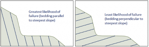
In the diagrams shown here, a road cut is constructed in sedimentary rock with well-developed bedding. On the left, draw in the orientation of the bedding that would represent the greatest likelihood of slope failure. On the right, show the orientation that would represent the least likelihood of slope failure.
](https://openpress.usask.ca/app/uploads/sites/29/2017/05/a-road-cut-.png)
Figure 15.31: Source: Steven Earle (2015) CC BY 4.0 View source
Figure 15.32: Source: Steven Earle (2015) CC BY 4.0 View source
Explain why moist sand is typically stronger than either dry sand or saturated sand.
In the context of mass wasting, how does a flow differ from a slide?
If a large rock slide starts moving at a rate of several metres per second, what is likely to happen to the rock, and what would the resulting failure be called?
In what ways does a debris flow differ from a mudflow?
In the situation described in the chapter regarding lahar warnings at Mt. Rainier, the residents of the affected regions have to assume some responsibility and take precautions for their own safety. What sort of preparation should the residents make to ensure that they can respond appropriately when they hear lahar warnings? What other considerations do officials have to make in their emergency plan, other than just sounding a warning?
What factors are likely to be important when considering the construction of a house near the crest of a slope that is underlain by glacial sediments?
15.6 Answers to Chapter Review Questions
- The shear force and normal force vectors are shown on the left-hand diagram:
- Based on the relative lengths of the arrows it appears that this material is stable, and unlikely to fail.
- If the shear strength was reduced by 25% (right-hand diagram) the material would be much closer to failure, but the strength (based on the length of the arrows) still appears to be greater than the shear force.
In moist sand the grains are each surrounded by an envelope of water, and the water envelopes overlap. The attractive surface tension of the water holds the grains together.
In a the material moves like a fluid (individual particles move independently). In a the mass moves as an intact unit, with little or no relative motion between grains or clasts.
If a large rock slide starts moving at a rate of several metres per second, the rock is very likely to break into smaller pieces. If the pieces are small and numerous enough that the material can flow, then it becomes a rock avalanche.
A debris flow is composed mostly of sand-sized and larger clasts, while a mudflow is composed mostly of sand-sized and smaller clasts.
Residents at risk from Mt. Rainier lahars need to know what the warnings mean and roughly how much time they have between receiving a warning and being in actual danger. They need to create a plan to exit their residence quickly, and they need to know which way to go to get to safety as efficiently as possible.
Some of the important factors include:
- The steepness of the slope
- Any existing erosion processes happening at the base of the slope (e.g., wave or stream erosion)
- The nature of surface or shallow sub-surface drainage in the upper part of the slope, and any effects that the construction might have on the drainage
- The weight of the building (unless it is to be constructed in an excavation that represents more mass than the building itself)
